Pictures of Flow measurement in existing manholes and sewers installed
Aus HST-Zangenberg GmbH & Co. KG
Inhaltsverzeichnis
- 1 Q³-BiK flow measurements as a retrofit
- 1.1 Inflow to the wastewater treatment plant
- 1.2 Inflow measurement in the sand trap
- 1.3 Inflow Aeration tank
- 1.4 Wastewater treatment plant outlet
- 1.4.1 Outlet WWTP Dillingen
- 1.4.2 Outlet WWTP Rheinfelden after a spillway chute
- 1.4.3 Outlet waste water plant Sasbach
- 1.4.4 Outlet waste water plant Bad Camberg
- 1.4.5 Outlet flow measurement in a plain manhole
- 1.4.6 System mostly under water
- 1.4.7 waste water plant Outlet after the secondary settlement tank.
- 1.4.8 Outlet wastewater plant Nürnberg
- 1.4.9 Outlet wastewater plant Lünen Seeseke Mündung
- 1.5 Settlement within communities and associations
- 1.5.1 Measurementpoint for settlement Switzerland
- 1.5.2 Measurementpoint for settlement Switzerland
- 1.5.3 Measurementpoint for in a existing old Venturi
- 1.5.4 Retrofitting in a 1m manhole
- 1.5.5 Q³-BiK in Polypropylen.
- 1.5.6 Flowmeasurement for settlement with accumulator
- 1.5.7 wastewater settlement measuring point
- 1.6 Industrial flowmeasurement
- 1.7 Chemiepark Abwasser-Durchflussmessstellen
- 1.7.1 Durchflussmengenabrechnung Einzelbetrieb in krummer Kanalführung eingepasst
- 1.7.2 Durchflussmengenabrechnung Einzelbetrieb
- 1.7.3 3 Zuläufe in ein Sammelbecken und eine Durchflussmengenmessung
- 1.7.4 Durchflussmengenabrechnung im 1m Rundschacht
- 1.7.5 Durchflussmengenabrechnung im Rechteckschacht 1x1m
- 1.7.6 Durchflussmengenabrechnung Einzelbetrieb im Chemiepark
- 1.7.7 Nachrüstung in alte Venturi Messstelle
- 1.8 Deponien
- 1.9 Talsperren
Q³-BiK flow measurements as a retrofit
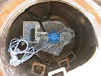
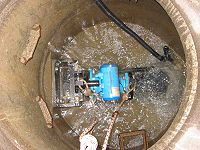
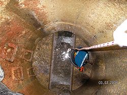
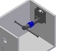
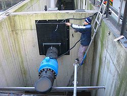
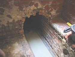
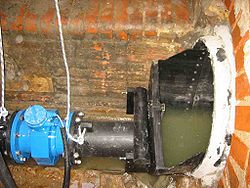
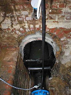
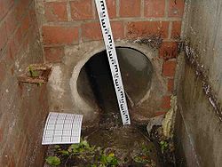
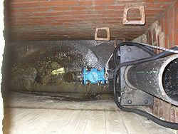
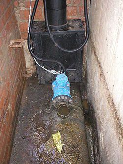
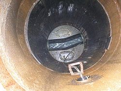
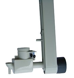
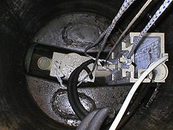
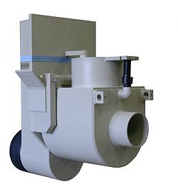
This application images show how the measuring point looked after installation an Q ³ BiK flowmeasurementsystem.
Inflow to the wastewater treatment plant |
|
|
|
Treatment plant Leipzig: 3 inflows in one manhole |
|
|
|
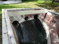 |
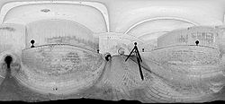 |
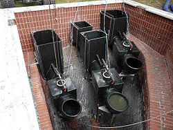 |
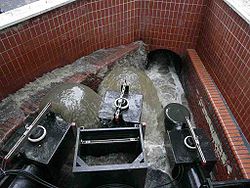 |
| 3 inlets diameter 800-1000mm |
3D laser scanning for measuring the geometry |
Applied systems |
In operation |
WWTP Mertzig Luxembourg |
|
|
|
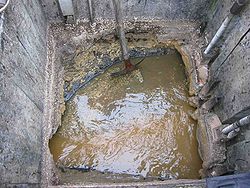
|
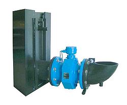
|
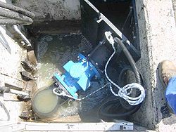
|
|
| Existing distributor shaft |
Q³-BiK System |
Adapted in the corner. |
|
WWTP inflow Binningen with simple inlet flowcontrol |
|
|
|
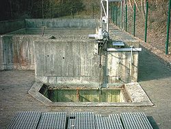
|
|
|
|
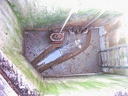
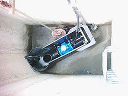
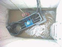
| Look at the outlet of the storming tank before the treatment plant |
Empty manhole |
System adapted at the outlet of the shaft. |
|
WWTP inflow Hundsangen in the Venturi flume mounted |
|
|
|
|
|
|
|
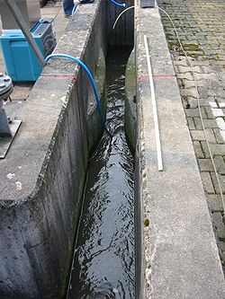
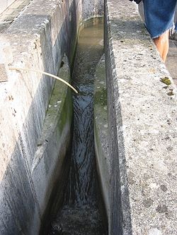
| Old existing Venturi |
|
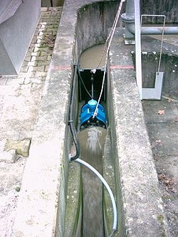
Q³-BiK SW installed before the Venturi. No remodelling necessary |
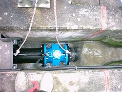
View from ubove |
WWTP inflow Zürich Kloten -
|
|
|
|
|
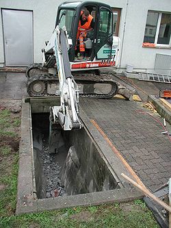
|
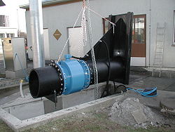
|
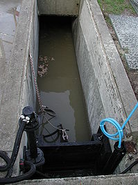
|
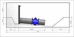
| Planning |
Old Venturi was dredged. |
Installation |
The system is under water. |
Inflow measurement in the sand trap |
|
|
|
WWTP Lampertheim |
|
|
|
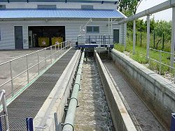 |
|
 |
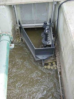 |
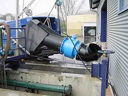
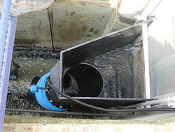
| Sand trap |
Mounting in a empty sand trap |
No water. Filling the sand trap |
Measurement is ready whne the sand trap is full. |
WWTP Heimbuchental Sand trap |
|
|
|
|
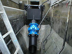 |
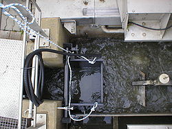 |
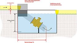 |
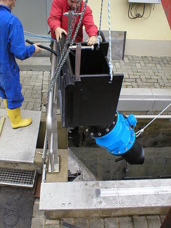
| Installation |
Mounted in the outlet of the sand trap |
|
more information (Google translated) |
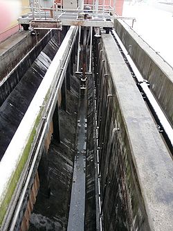
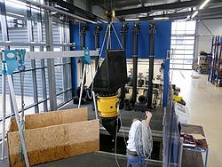
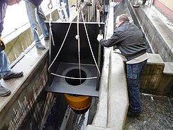
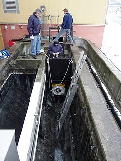
WWTP Kandel Sand trap inflow measurement |
|
|
|
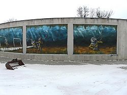 |
 |
|
 |
| Art on the WWTP Kandel |
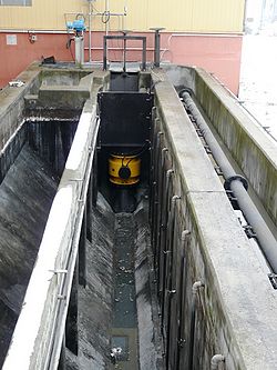
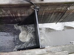
Sand trap before installation | Q³-BiK System on the test-and calibration stand | System while installation in the sand trap |
|
|
|
|
| Mounting | Mounted - empty sand trap | Filling the sand trap. | |
Inflow Aeration tank |
|
|
|
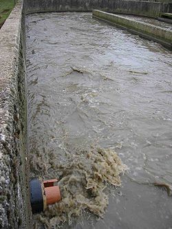
Inflow diretly to aeration basin. |
|
|
|
|
|
|
|
| aeration basin WWTP Grossbusch Luxembourg |
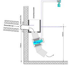
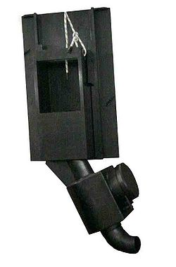
priciple sketch | System |
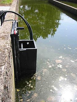
Mounted in aeration basin |
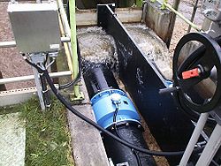
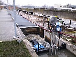
Flow distribution to 4 aeration basin |
|
|
|
 |
 |
 |
 |
| WWTP Mainz |
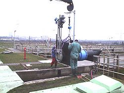
During installtion the flow can stopped for maximum 2 hours. |
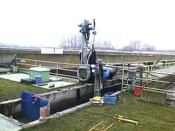
2 flowmeasurements in one flume. Distributed to the right and the left basin. |
|
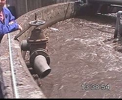
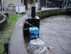
Inflow by pumps to the aeration basin |
|
|
|
 |
 |
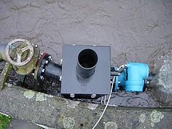 |
|
| Original state. Inflow aeration basin. From the buffer pool is pumped into aeration basin . | Q ³ BiK mounted on the hand valve. |
Q ³ BiK from above. Calming box with vent . | |
Wastewater treatment plant outlet
|
|
|
|
Outlet WWTP Dillingen |
|
|
|
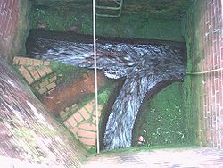
|
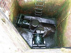
|
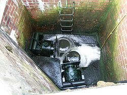
|

|
| |
Very close fitting. warped piping. Two systems in one manhole | Short design made possible by the special calibration on ourtest-and calibration stand . | The two measurements do not influence each other, although they converge in a shaft. |
Outlet WWTP Rheinfelden after a spillway chute |
|
|
|
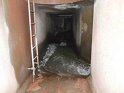
|
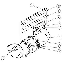
|
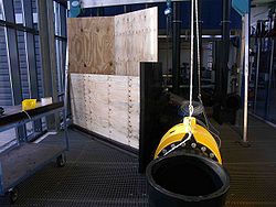
|
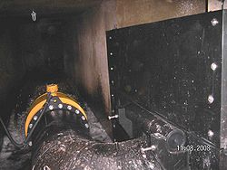
|
| View to the spillway chute on the right side |
|
Simulation on the test bench. |
Ready installed. Same view as picture 1 |
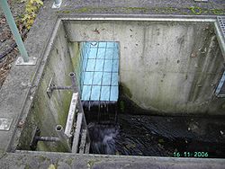
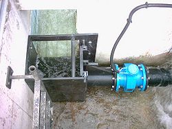
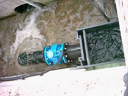
Outlet waste water plant Sasbach |
|
|
|
|
|
|
|
| Outlet after the secondary settlement tank. |
We use the different level to reduce the backflow. |
|
|
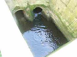
Outlet waste water plant Bad Camberg |
|
|
|
|
|
|
|
| Outlet on the right side. Left is the rrainwater bypass. |
|
Operating under water |
|
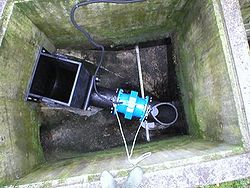
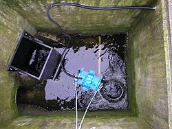
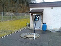
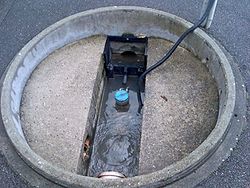
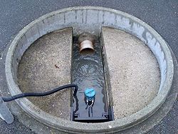
Outlet flow measurement in a plain manhole
|
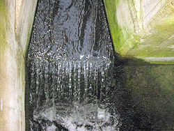
System mostly under water |
|
|
 |
 |
 |
|
| Assembly stand |
View in the inflow |
View to the outlet |
|
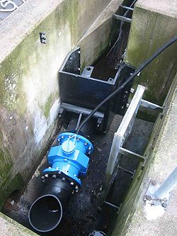
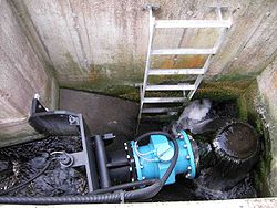
waste water plant Outlet after the secondary settlement tank. |
|
|
|
|
|
|
|
| Outlet open channel after the desecondary settlement tank |
We use the different in slope to built in a smaler system. |
|
|
Outlet wastewater plant Nürnberg
|
|
|
|
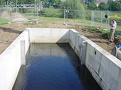
|

|
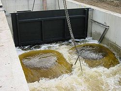
|
FILM |
| Existing 4m wide channel |
We make it possible to install during 3500 l/s flow |
|
|
Outlet wastewater plant Lünen Seeseke Mündung |
|
|
|
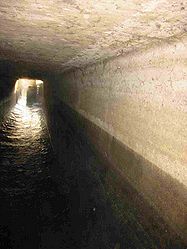
|

|
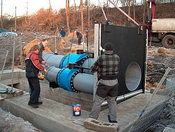
|
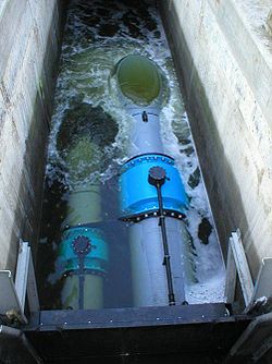
|
| Existing retangle channel |
Sliced. A separate channel. The construction of a separate channel could be avoided. |
Q³-BiK doublesystem for a better measurement dynamic. |
|
Settlement within communities and associations
|
|
|
|
Measurementpoint for settlement Switzerland |
|
|
|
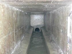
|
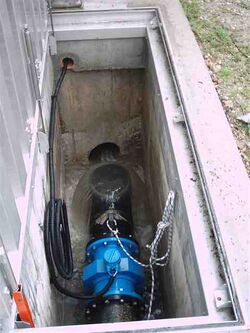
|
|
|
| Existing building |
For a better service the building was complete opened |
|
|
Measurementpoint for settlement Switzerland |
|
|
|
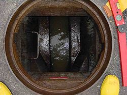
|
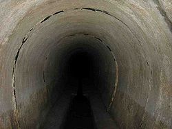
|
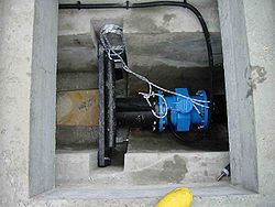
|
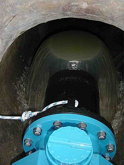
|
| Existing manhole with channel |
Special Profile |
Adapted Q³-Bik. New channel border |
|
Measurementpoint for in a existing old Venturi |
|
|
|
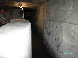
|
|
|
|
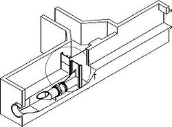
| Old Venturichannel |
Constructiongplan to rebuild a deeper channel. |
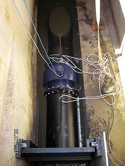
Mounting |
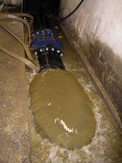
System partially under Water |
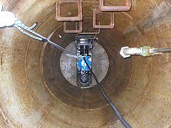
Retrofitting in a 1m manhole |
Q³-BiK in Polypropylen. |
Flowmeasurement for settlement with accumulator |
wastewater settlement measuring point
|
|
|
|

|
| |
For high temperature up to 80°C | in 1m manhole in a acre |
|
Industrial flowmeasurement |
|
|
|
Wastewater control with flow, pH and conductivity |
|
|
|
|
|
|
|
| Measuring the existing manhole before construction |
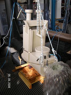
Measuring szstem on the testbench |
The pH and conductivity sensors can be disconnect from above. |
|
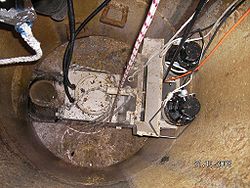
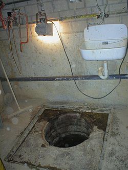
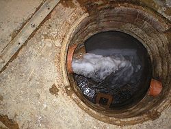
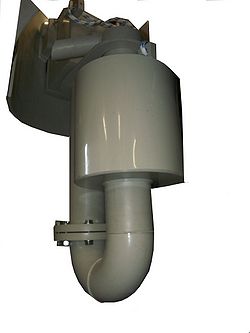
Flowmeasurement in wastewater from a ceramic company |
|
|
|
|
|
|

|
| Manhole entry |
The inflow is directly under the cover |
Inlet to mount from above |
Wire in a protection hose. System can be disconnect from above |
Flowmeasurement in a meat factory |
|
|
|
|
|
|
|
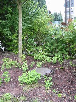
| Manholecover. |
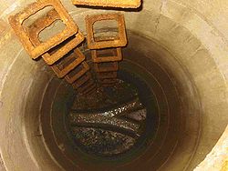
Channel to the sewer |
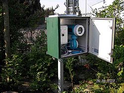
Flowmeter display in a protection housing |
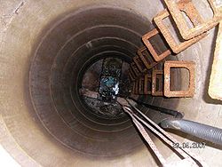
mounte dQ³-BiK |
Steel industry. Outlet to the wastewater plant |
|
|
|

|
|
|
|
| |
3D sketch |
|
|
Fertilizers factory |
|
|
|
 |
 |
 |
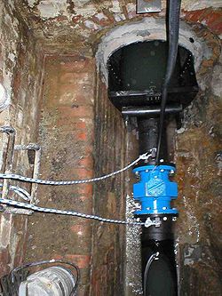 |
| View in the outlet |
adapted in the assymetric threat |
Above is the Ultrasonic Levelmeasurment. To detect the emergency overflow and dirt detection. | |
Zementfabrik Übergabestelle an den Abwasserverband |
|
|
|
 |
 |
 |
|
| Sondierung |
|
|
|
Chemiepark Abwasser-Durchflussmessstellen
|
|
|
|
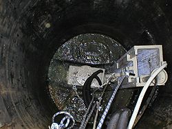
Durchflussmengenabrechnung Einzelbetrieb in krummer Kanalführung eingepasst |
|
|
|
|
|
|
|
| Krumme Kanalführung im Schacht |
|
Q³-BiK mit Staukasten an den krummen Kanal angepasst. |
In Betrieb. |
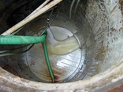
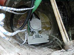
Durchflussmengenabrechnung Einzelbetrieb
|
|
|
|
|
|
|
|
| |
|
|
|
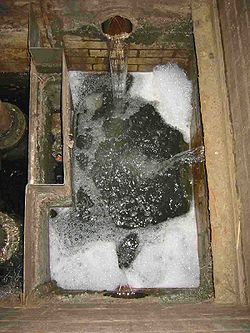
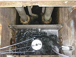
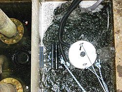
3 Zuläufe in ein Sammelbecken und eine Durchflussmengenmessung
|
|
|
|
|
|
|
|
| Sammelbecken. Abfluss nach links |
Q³-BiK wird eingeklappt und mit Gewichten unter Wasser gehalten. |
|
|
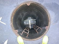
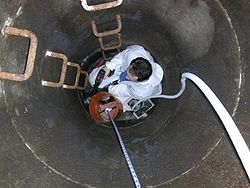
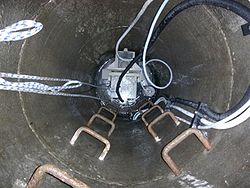
Durchflussmengenabrechnung
|
|
|
|
|
|
|
|
| |
Montage |
|
|
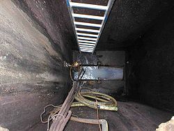
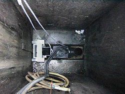
Durchflussmengenabrechnung im Rechteckschacht 1x1m
|
|
|
|
|
|
|
|
| |
|
|
|
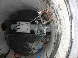
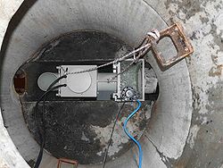
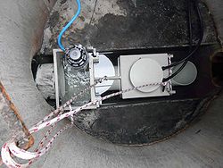
Durchflussmengenabrechnung Einzelbetrieb im Chemiepark |
|
|
|
|
|
|
|
| |
|
|
|
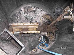
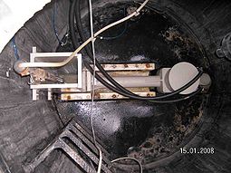
Nachrüstung in alte Venturi Messstelle |
|
|
|
|
|
|
|
| Alter Venturi-Einsatz blieb drin, um keine Umdichtigkeiten bei Ausbau zu erzeugen. | System wurde mit langem Zulauf ausgestattet, damit der breitere Messaufnehmer nach dem Venturi ist. |
|
|
Deponien
|
|
|
|
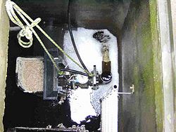
Deponiesickerwasser. |
|
|
|
 |
 |
|
|
|
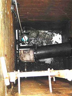
Deponie Leonberg Messstelle 1 |
Deponie Leonberg Messstelle 2 | |
|
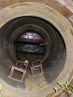
Deponie Tuningen |
|
|
|
 |
 |
 |
 |
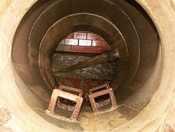
| Schacht vorher. |
Ablauf der Depüonie ist das obenliegende Rohr mit schiessendem Wasser. |
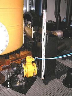
Q³-BiK Durchflussmessung auf dem Prüfstand |
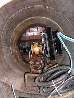
Eingebauter Messaufnehmer Q³-BiK mit Einfädeltrichter (Film) |
Talsperren |
|
|
|
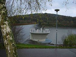
Talsperre Sickerwassermessung |
|
|
|
 |
 |
 |
|
| |
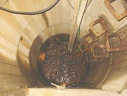
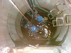
Sickerwassersammelschacht |
2 Zuflüsse mit je einem Q³-BiK Durchflussmesssystem |
|
|
|
|
|
|
| |
|
|
|
| |
|
|
|
| |
|
|
|
| |
|
|
|
| |
|
|
|
| |
|
|
|
| |
|
|
|
| |
|
|
|
| |
|
|
|
| |
|
|
|
| |
|
|
|
| |
|
|
|
| |
|
|
|
| |
|
|
|
| |
|
|
|
